When it comes to Metal Core Printed Circuit Boards (MCPCBs), one of the most frequently asked questions is about the minimum trace width and spacing. As a trusted MCPCB supplier, I've encountered this query numerous times from our clients, and I understand the importance of getting it right. In this blog, I'll delve into the factors that determine the minimum trace width and spacing for MCPCBs and how these parameters impact the overall performance of your boards.
Understanding MCPCBs
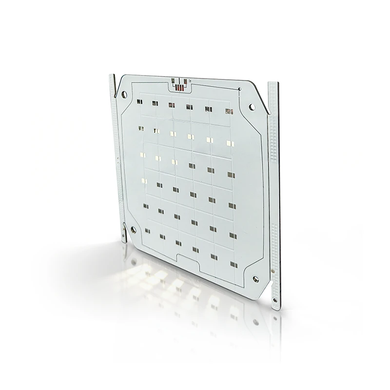
Before we dive into the specifics of trace width and spacing, let's briefly recap what MCPCBs are. MCPCBs are a type of printed circuit board that features a metal core, typically aluminum or copper, which provides excellent thermal conductivity. This makes them ideal for applications that require efficient heat dissipation, such as LED lighting, power supplies, and automotive electronics. The metal core is separated from the circuit layer by a thin layer of dielectric material, which insulates the electrical traces from the metal base.
Factors Affecting Minimum Trace Width
The minimum trace width for an MCPCB is determined by several factors, including the electrical current carrying capacity, the manufacturing process, and the design requirements. Let's take a closer look at each of these factors:
Electrical Current Carrying Capacity
One of the primary considerations when determining the minimum trace width is the amount of electrical current that the trace will need to carry. The wider the trace, the more current it can handle without overheating. This is because a wider trace has a lower resistance, which reduces the amount of power dissipated as heat. To calculate the minimum trace width required for a given current, you can use the IPC-2221 standard, which provides guidelines for trace width and current capacity based on the copper thickness, temperature rise, and other factors.
Manufacturing Process
The manufacturing process also plays a significant role in determining the minimum trace width for an MCPCB. The ability to produce fine traces depends on the capabilities of the PCB fabrication equipment and the quality of the materials used. Advanced manufacturing techniques, such as laser direct imaging (LDI) and photolithography, can achieve finer trace widths compared to traditional methods. However, these techniques also come with higher costs, so it's important to balance the desired trace width with the budget and production volume.
Design Requirements
The design requirements of your MCPCB, such as the component density, signal integrity, and mechanical constraints, can also influence the minimum trace width. In high-density designs, where space is limited, you may need to use narrower traces to fit all the components and connections on the board. However, this can increase the risk of signal interference and crosstalk, so it's important to carefully consider the trade-offs between trace width and signal integrity.
Factors Affecting Minimum Trace Spacing
In addition to the trace width, the minimum trace spacing is another critical parameter that affects the performance and reliability of an MCPCB. The trace spacing refers to the distance between adjacent traces on the board, and it is determined by several factors, including the electrical insulation requirements, the manufacturing process, and the design requirements.
Electrical Insulation Requirements
The primary function of the trace spacing is to provide electrical insulation between adjacent traces and prevent short circuits. The minimum trace spacing required depends on the voltage between the traces, the dielectric constant of the insulating material, and the environmental conditions. To ensure proper electrical insulation, you can refer to the IPC-2221 standard, which provides guidelines for trace spacing based on the voltage rating and other factors.
Manufacturing Process
Similar to the trace width, the manufacturing process also affects the minimum trace spacing that can be achieved. The ability to produce narrow trace spacing depends on the resolution of the PCB fabrication equipment and the quality of the materials used. Advanced manufacturing techniques, such as LDI and photolithography, can achieve finer trace spacing compared to traditional methods. However, these techniques also require more precise alignment and control, which can increase the risk of manufacturing defects.
Design Requirements
The design requirements of your MCPCB, such as the component density, signal integrity, and mechanical constraints, can also influence the minimum trace spacing. In high-density designs, where space is limited, you may need to use narrower trace spacing to fit all the components and connections on the board. However, this can increase the risk of signal interference and crosstalk, so it's important to carefully consider the trade-offs between trace spacing and signal integrity.
Balancing Trace Width and Spacing
When designing an MCPCB, it's important to find the right balance between the trace width and spacing to ensure optimal performance and reliability. A wider trace width can increase the current carrying capacity and reduce the risk of overheating, but it also requires more space on the board. On the other hand, a narrower trace spacing can increase the component density and reduce the size of the board, but it also increases the risk of signal interference and short circuits.
To find the optimal trace width and spacing for your MCPCB, you can use a combination of simulation tools and design guidelines. Simulation tools, such as SPICE and FEM, can help you analyze the electrical performance of your design and identify potential issues before fabrication. Design guidelines, such as the IPC-2221 standard, can provide you with recommended values for trace width and spacing based on the specific requirements of your application.
Importance of Working with a Reliable MCPCB Supplier
As an MCPCB supplier, we understand the importance of providing high-quality boards that meet the specific requirements of our clients. That's why we invest in the latest manufacturing equipment and technologies to ensure that we can produce MCPCBs with fine trace widths and narrow trace spacing. Our experienced engineers and technicians work closely with our clients to understand their design requirements and provide them with customized solutions that meet their needs.
In addition to our manufacturing capabilities, we also offer a range of value-added services, such as design review, prototyping, and testing, to ensure that our clients' MCPCBs are reliable and perform as expected. We use advanced testing equipment and techniques to verify the electrical performance, thermal performance, and mechanical integrity of our boards, and we provide detailed test reports to our clients.
Conclusion
In conclusion, the minimum trace width and spacing for an MCPCB are critical parameters that affect the performance and reliability of the board. The trace width and spacing are determined by several factors, including the electrical current carrying capacity, the manufacturing process, and the design requirements. To ensure optimal performance and reliability, it's important to find the right balance between the trace width and spacing and to work with a reliable MCPCB supplier who has the experience and capabilities to produce high-quality boards.
If you're looking for an MCPCB supplier who can provide you with customized solutions and high-quality boards, please don't hesitate to contact us. We'd be happy to discuss your requirements and provide you with a quote. You can also visit our website to learn more about our Aluminum PCB products and services.
References
- IPC-2221: Generic Standard on Printed Board Design
- IPC-2152: Standard for Determining Current-Carrying Capacity in Printed Board Design


