Solder QFN components properly in SMT assembly is crucial for a successful PCB build. As an SMT assembly supplier, I've dealt with my fair share of QFN soldering challenges, and I'm here to share some tips on how to get it right.
Understanding QFN Components
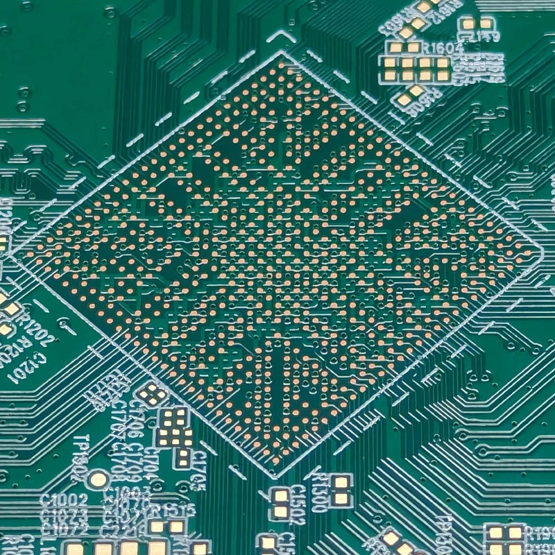
First off, let's talk about what QFN components are. QFN stands for Quad Flat No-leads. These components are small and have a footprint on the PCB. They have contacts on the bottom, which makes them a bit tricky to solder compared to some other types of components. They're popular because they're compact and can offer good electrical performance. But that also means you've got to be really careful when soldering them.
Preparing for Soldering
Stencil Design
The first step is to make sure your stencil is designed correctly. The stencil is like a cookie cutter for your solder paste. It puts the right amount of paste in the right places on the PCB. For QFN components, the stencil apertures need to be sized just right. If they're too big, you might end up with too much solder, which can cause shorts. If they're too small, you won't have enough solder, and the joint might be weak.
Solder Paste Selection
You also need to choose the right solder paste. There are different types out there, and you want to pick one that's suitable for your specific application. Factors to consider include the alloy composition, particle size, and flux type. The alloy affects the melting point and the mechanical properties of the solder joint. The particle size affects how well the paste prints through the stencil. And the flux helps clean the surfaces and promotes good wetting.
PCB Cleaning
Before you start soldering, it's important to clean the PCB. Any dirt, dust, or oxidation on the PCB can prevent the solder from adhering properly. You can use a PCB cleaner or isopropyl alcohol to clean the board. Make sure to dry it thoroughly before applying the solder paste.
Applying Solder Paste
Stencil Printing
Once you've got your stencil and solder paste ready, it's time to apply the paste to the PCB. Stencil printing is the most common method for this. You place the stencil on top of the PCB and use a squeegee to spread the solder paste over the apertures. The paste gets pushed through the apertures and onto the PCB pads. It's important to use the right pressure and speed when using the squeegee. Too much pressure can cause the paste to spread outside of the pads, and too little pressure might not deposit enough paste.
Inspection
After printing, you should inspect the solder paste deposits. You can use a microscope or an automated optical inspection (AOI) system to check for any errors. Look for things like missing paste, excess paste, or smudged deposits. If you find any issues, you can try to correct them before placing the QFN component.
Placing the QFN Component
Pick-and-Place Machine
Most SMT assembly suppliers use a pick-and-place machine to place the QFN component on the PCB. The machine uses a vacuum nozzle to pick up the component and place it precisely on the solder paste deposits. It's important to make sure the machine is calibrated correctly so that the component is placed in the right position.
Manual Placement
In some cases, you might need to place the component manually. This can be more challenging, but it's doable. You'll need a pair of tweezers and a steady hand. Make sure to align the component properly with the solder paste deposits on the PCB.
Reflow Soldering
Reflow Oven
Once the component is placed, it's time to reflow the solder. This is usually done in a reflow oven. The oven heats the PCB and the solder paste to a specific temperature profile. The temperature profile is designed to melt the solder paste, allow it to flow and form a good joint, and then cool it down to solidify the joint.
Temperature Profile
The temperature profile is really important. If the temperature is too low, the solder might not melt properly, and you'll end up with a weak joint. If the temperature is too high, you could damage the component or the PCB. You need to adjust the temperature profile based on the type of solder paste and the component you're using.
Inspection and Testing
Visual Inspection
After reflow soldering, you should do a visual inspection of the solder joints. Look for any signs of poor soldering, such as cold solder joints, shorts, or missing connections. You can use a microscope or a magnifying glass to get a closer look.
X-ray Inspection
For QFN components, X-ray inspection is often a good idea. Since the contacts are on the bottom of the component, it can be difficult to see the solder joints just by looking at the top of the board. X-ray inspection can show you what's going on inside the joint and help you detect any hidden defects.
Functional Testing
Finally, you should do some functional testing on the PCB. This involves powering up the board and checking that all the components are working correctly. If there are any issues, you might need to troubleshoot and rework the board.
Troubleshooting Common Issues
Cold Solder Joints
Cold solder joints are a common problem in QFN soldering. They look dull and grainy instead of shiny and smooth. This can be caused by a variety of factors, such as improper temperature profile, dirty surfaces, or insufficient solder paste. To fix a cold solder joint, you can reheat the joint using a soldering iron or a rework station.
Shorts
Shorts can occur when there's too much solder between two adjacent contacts. This can cause the electrical signals to flow where they're not supposed to, which can lead to malfunctioning of the circuit. To fix a short, you can use a desoldering tool to remove the excess solder.
Lifted Pads
Lifted pads can happen if the PCB is heated too much or if the soldering process is too aggressive. This can cause the pads to lift off the PCB, which can make it difficult to make a good electrical connection. To fix a lifted pad, you might need to repair the PCB or replace the component.
Conclusion
Soldering QFN components in SMT assembly is a challenging but achievable task. By following the steps outlined above and paying attention to the details, you can increase your chances of getting a successful solder joint. If you're looking for high-quality SMT assembly services, including Mixed Technology PCB Assembly, SMT PCB Assembly and SMT BGA Assembly, don't hesitate to get in touch with us. We'd love to discuss your project and how we can help you achieve your goals.
References
- Printed Circuit Board Assembly Handbook
- IPC standards for soldering and assembly


