


Overview
A data acquisition board can be assembled correctly and still deliver poor measurement performance.
The solder joints may be acceptable. The firmware may boot. The ADC may return numbers. None of those facts, by themselves, prove that the board is preserving the signal the product was designed to measure.
For data acquisition PCBA manufacturing, the production goal is not simply to build a board that powers on. It is to preserve the approved measurement path from the sensor input through signal conditioning and conversion, keep the hardware and firmware configuration aligned, and verify the functions that production is responsible for.
A simple condition-monitoring module and a multichannel instrumentation PCBA may both acquire sensor data, but they do not automatically need the same sourcing controls, cleaning process, calibration method, fixture, or production test.
The manufacturing plan should follow the measurement requirement.
Start at the Connector, Not the SMT Line
When reviewing a sensor-interface or data-acquisition PCBA, it is often more useful to start with one measurement channel than with the assembly process.
Pick the point where the real-world signal enters the board. Then follow that channel until the product produces usable data.
|
Measurement Stage |
Question for Manufacturing |
|
Sensor or field input |
What signal reaches the channel, and what range or interface matters? |
|
Protection or isolation |
Which approved components protect or isolate the input, if the design requires them? |
|
Analog front end |
Which amplifiers, filters, resistor networks, multiplexers, or other parts shape the measurement? |
|
ADC and reference |
Which converter, reference, and supporting components belong to the approved configuration? |
|
Firmware or configuration |
Does software control gain, channel selection, sampling, calibration data, or signal processing? |
|
Production verification |
What known input should production apply, and what result should the board return? |
Not every board contains every block.
That is exactly why a generic industrial PCBA checklist is rarely enough for this type of project.
The first useful question is not:
How many bits is the ADC?
It is:
What does this channel actually have to measure?
A sensor-interface board may receive a conditioned voltage, a current loop, a bridge sensor, a temperature input, a vibration signal, a pressure transducer, or another field signal.
Those inputs can lead to very different decisions around gain, protection, isolation, test stimulus, and calibration.
Before functional-test planning, the OEM and EMS team should be clear on points such as:
- sensor or signal type;
- relevant input range;
- channel mapping;
- single-ended or differential input;
- sensor excitation where applicable;
- isolation requirements where applicable;
- normal and fault conditions production must verify;
- whether production is proving basic response or a defined measurement result.
"It reads the sensor" is not an executable production requirement.
A technician can know where to connect the cable and still have no idea what the test is supposed to prove.
What Production Must Preserve
Once the signal path is understood, the manufacturing question becomes more concrete:
Which parts of the released design have to stay controlled for that measurement path to remain valid?
The Parts That Actually Affect the Measurement
Not every component deserves the same substitution rule.
On a sensor interface or instrumentation PCBA, some parts can directly influence measurement behavior.
Depending on the circuit, they may include:
- ADCs;
- voltage references;
- instrumentation or operational amplifiers;
- analog multiplexers;
- gain-setting or precision resistor networks;
- signal-path filter components;
- isolation devices;
- input-protection devices.
An alternate that matches the package and footprint is not automatically equivalent.
Offset, drift, noise, bias current, bandwidth, settling behavior, leakage, reference characteristics, or input capacitance may matter in a particular circuit.
Most BOM lines will not need that level of review. The tighter approval boundary belongs around components that can materially change the measurement path.
Replacing a status LED and replacing the voltage reference feeding an ADC are both BOM changes.
They are not the same engineering decision.
For sourcing and repeat production, that distinction matters more than simply having a second part number available.
Where the EMS Provider Should Stop
Grounding, return-current behavior, filter design, protection topology, reference routing, and ADC drive conditions belong primarily to the electrical design.
A good assembly process cannot repair an unstable signal chain.
Production should not quietly redesign one either.
When manufacturing or test preparation exposes a concern, the normal path is to raise it for engineering review rather than improvise a new analog architecture on the factory floor.
Manufacturing control has a different job:
- use the approved PCB and BOM revisions;
- install the correct component values and approved alternates;
- maintain assembly requirements;
- load the correct firmware;
- control approved deviations;
- manage rework;
- execute the approved production test.
Manufacturability review and analog circuit design are related, but they are not the same responsibility.
If deeper analog design review is part of the supplier's scope, that should be agreed separately.
When Assembly Conditions Become Electrical Conditions
Many sensor-interface problems do not look like workmanship problems.
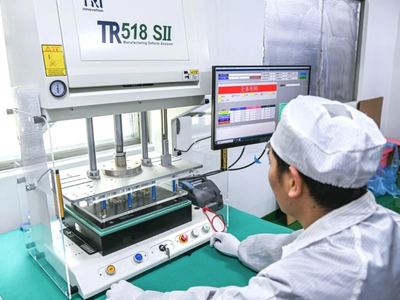
AOI can confirm that an amplifier is present and correctly oriented. It cannot prove that the channel gain is correct.
X-ray can help evaluate hidden solder joints. It cannot prove that the assembled signal chain meets the required measurement behavior.
A PCBA can power up and communicate while:
- the wrong precision component is installed;
- two channels are mapped incorrectly in firmware;
- an approved alternate affects a sensitive input;
- contamination influences a high-impedance node;
- a measurement-critical area has been reworked;
- the production test never applies the condition that would expose the problem.
Inspection tells you something about the build.
Measurement verification tells you something different.
One should not be used as a substitute for the other.
Cleanliness
For many sensor PCBAs, the normal approved assembly process is entirely adequate.
At the high-impedance or very-low-current end of the spectrum, surface condition can become part of the electrical problem.
Flux residue, moisture, handling contamination, or other surface contamination can create leakage paths that matter in sensitive circuits.
Most data acquisition boards do not need a special cleaning route simply because they contain analog circuitry.
The question is whether the particular measurement path is sensitive enough that surface condition needs to be controlled as an electrical requirement.
If it is, the project should define the appropriate cleaning, handling, verification, or acceptance condition.
If it is not, extra processing adds cost without solving a real requirement.
Isolation
Industrial sensor systems often use galvanic isolation.
Many do not.
Where isolation is part of the approved architecture, manufacturing may need to preserve requirements around:
- isolation components;
- the isolation barrier;
- creepage and clearance;
- assembly condition;
- customer-defined electrical verification.
A non-isolated data acquisition board does not need a dielectric-withstand test simply because another industrial project uses one.
The control should follow the electrical architecture, not the industry label.
A PASS Result Is Only as Good as the Test Behind It
Once the board is assembled, the question changes.
Production now has to prove that the channel behaves as intended.
A sensor-interface board can pass a functional test while the test itself proves very little.
Consider an instruction such as:
Apply a signal and check that the reading changes.
That may prove that the path is alive.
It does not necessarily prove correct gain, channel mapping, offset, range, calibration, or another measurement requirement.
The production test should reflect what the OEM actually needs verified.
FCT and Calibration Are Different Jobs
Functional testing and calibration may happen at the same station, but they answer different questions.
Functional testing asks whether the assembled board performs the functions defined in the production test procedure.
Calibration establishes the relationship between a known reference and the value reported by the product.
Adjustment or correction, where required, is a separate step.
Some data acquisition PCBAs require per-unit calibration. Others do not.
If calibration is part of production, the process may need to define:
- reference stimulus;
- reference equipment;
- applicable channels;
- firmware or software revision;
- coefficient or adjustment method;
- acceptance limits;
- where calibration data is stored;
- what happens after rework or reprogramming;
- how the resulting record is associated with the unit or batch.
A high-resolution ADC does not, by itself, create a requirement for production calibration.
Calling a functional check "calibration" does not make it one either.
Test the Product Requirement, Not the ADC Datasheet
The ADC is one part of a larger signal chain.
The final measurement can also depend on the input stage, amplifier, reference, filter, protection network, power supply, PCB layout, firmware, and calibration strategy.
Production limits should therefore come from the approved product requirement, not simply from statements such as:
16-bit ADC
or:
24-bit converter.
For one board, applying a defined sensor stimulus and confirming the expected response may be sufficient.
For another, production may need several controlled input points, channel-specific limits, a calibrated source, or customer-supplied software.
A useful review question is:
What failure would this test actually catch?
If nobody can answer that clearly, a green PASS indicator does not provide much engineering confidence.
The Test Setup Is Part of the Measurement
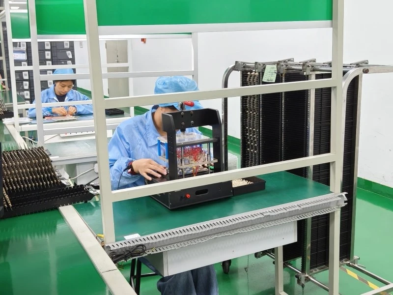
The PCBA is not the only thing in the electrical path during production testing.
The setup may include:
reference source -> cable -> switching or relay -> fixture contact -> connector -> PCBA input
Depending on the signal being measured, contact resistance, grounding, shielding, leakage, cable routing, switching behavior, or ordinary instrument variation may influence the result.
A simple industrial voltage-input board does not need the same fixture discipline as a very high-impedance or low-level measurement channel.
But the fixture should not automatically be treated as electrically invisible.
There is also a practical limit to what a station can enforce.
If normal variation in the reference source, fixture, cable, contacts, and measurement equipment is large enough to blur the specified pass/fail boundary, the station will have difficulty separating a marginal board from normal test-system variation.
That does not mean every DAQ project needs a metrology laboratory on the production floor.
It means the test system has to be capable of making the decision assigned to it.
This is much easier to address during DFT and NPI than after supposedly good boards begin failing intermittently at final test.
A Golden Unit Is Useful, but It Is Not Automatically a Calibration Standard
A known-good unit can be extremely useful in production.
It can help:
- check fixture operation;
- correlate test stations;
- troubleshoot unexpected failures;
- confirm software or configuration changes;
- verify that a test setup still behaves as expected.
That does not automatically make the unit a calibration reference.
The PCBA itself has component tolerances, measurement error, configuration history, and aging.
If a golden unit is intended to serve as part of the measurement or calibration standard, that role should be explicitly defined and controlled.
Otherwise, keep the distinction clear:
A known-good unit helps confirm the production setup.
A known reference establishes the measurement value.
Those are related jobs, not identical ones.
Engineering Characterization Is Not Routine Production Testing
During development, engineering may spend hours characterizing a board.
That work can include:
- noise analysis;
- gain and linearity checks;
- channel-to-channel comparison;
- temperature behavior;
- common-mode behavior;
- environmental testing;
- detailed oscilloscope or spectrum measurements.
Those results can be valuable.
They do not automatically belong in the test cycle of every production unit.
Engineering characterization asks:
What can this design do across the conditions that matter?
Production testing asks:
Did this manufactured unit or batch pass the checks required for release?
Use engineering characterization to decide what production must control.
Do not simply copy the development bench onto the production line.
The First Build Is Not the Hard Part
A working prototype proves that the design can work.
Repeat production asks a harder question:
Can the approved measurement behavior survive controlled manufacturing changes?
That is where configuration, rework, component sourcing, firmware, fixtures, and test revisions begin to matter as one system.
Keep Hardware, Firmware, Calibration, and Test on One Baseline
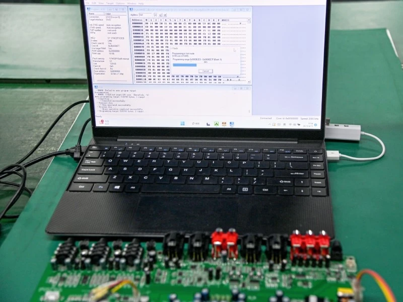
Data acquisition products often cross the hardware/software boundary.
Firmware may influence:
- channel selection;
- gain;
- sensor configuration;
- sampling;
- digital filtering;
- offset correction;
- calibration coefficients;
- unit-specific data.
A physically correct PCBA can still report the wrong measurement if the wrong configuration is loaded.
Depending on the project, the production baseline may include:
PCB revision + BOM revision + firmware revision + calibration method + test revision
The operator should not have to decide which firmware image or coefficient file "looks right" for a particular board.
Those decisions belong upstream in configuration control.
Rework Changes the Question
Replacing a damaged connector may require one level of verification.
Replacing a voltage reference, gain-setting network, front-end amplifier, or another measurement-critical component may require another.
Neither of these blanket rules is very useful:
Every reworked DAQ board must be recalibrated.
A final PASS is enough after every repair.
A better question is whether the rework touched a component or signal-chain stage that can affect the approved measurement requirement.
If it did, the appropriate retest, calibration, or engineering review should follow.
What Happens on the Next Build?
Later production may introduce:
- a new material lot;
- an approved alternate;
- a PCB revision;
- a firmware update;
- a replacement fixture;
- rework;
- a changed calibration method;
- a different component source.
Not every change requires full product requalification.
But a change that touches the measurement path should not disappear inside an ordinary production update.
Suppose a second-source amplifier is proposed.
The manufacturing question is:
Can we source and assemble it?
The product question is:
Does the approved measurement requirement still hold?
The EMS provider can manage the as-built configuration and flag the change.
The OEM engineering team should normally own the performance approval unless another responsibility has been agreed.
That keeps sourcing flexibility from quietly becoming product redesign.
Qualification Is Not Routine Screening
Industrial sensor equipment may be designed for temperature extremes, vibration, humidity, electrically noisy machinery, or other demanding environments.
Those conditions matter.
But a qualification test does not automatically become a production-screening requirement.
One project may use temperature cycling during design validation.
Another may require selected production screening.
A third may only require a defined functional test under normal factory conditions.
The manufacturing plan should follow the approved requirement.
Copying every environmental test from product qualification into routine production is not automatically more rigorous. Sometimes it is simply unnecessary.
Not Every Sensor Board Deserves the Same Process
"Sensor interface PCBA" covers a wide range of products.
A board that reads a digital sensor and reports a threshold does not need the manufacturing plan of a multichannel measurement instrument.
A straightforward monitoring device may not require:
- per-unit calibration;
- special cleaning;
- deep analog characterization;
- individual measurement records;
- environmental screening.
At the other end of the spectrum, an instrumentation PCBA may care deeply about low-level inputs, drift, channel matching, isolation, reference stability, calibration, and repeatability.
Calling every board "high precision" creates cost without improving the requirement.
Treating every sensor board like an ordinary digital controller can hide genuine risk.
The useful question is not:
What is the most rigorous process we can apply?
It is:
What does this product actually need production to control?
Edge Processing Does Not Fix Bad Input Data
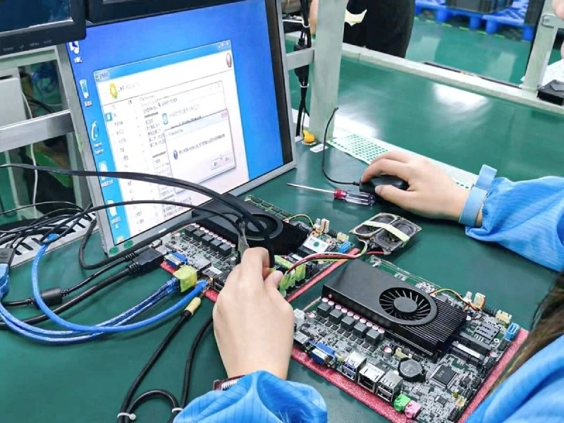
More condition-monitoring systems now process data closer to the machine, but that does not reduce the importance of the acquisition path. Software can only work with the data it receives.
If an input clips, the wrong calibration file is loaded, or a measurement-critical component changes without the necessary approval, downstream analytics start with compromised data.
What I Would Want Defined Before Production Release
Before releasing a sensor-interface or data-acquisition PCBA into repeat production, I would want clear answers to these questions.
What enters the channel?
Define the sensor or signal type and the range production needs to understand.
What result is production responsible for proving?
Basic detection, threshold response, measurement value, channel behavior, calibration, or something else?
Which BOM items are measurement-critical?
Identify the components where substitution needs additional engineering control.
Are cleanliness or isolation special requirements for this design?
Do not assume them. Do not leave them undefined when they matter.
Which hardware, firmware, calibration, and test revisions belong together?
Give production one approved baseline.
What known stimulus and test setup are needed?
Define the input source, fixture, cable, software, reference equipment, and PASS/FAIL logic where applicable.
Which changes require another engineering decision?
Set the boundary for alternates, revisions, rework, calibration changes, and test updates.
If those answers are clear, a technically sophisticated data acquisition board can still be straightforward to manufacture.
If they are vague, adding more inspection after assembly rarely fixes the underlying problem.
Where STHL Fits Into the Project
Shenzhen STHL Technology Co., Ltd. (STHL) supports industrial PCBA and EMS applications that include industrial sensor interface boards, sensor interfaces used in automation lines, and industrial instruments.
For buyers evaluating this type of project, STHL's Industrial EMS Solutions page provides the broader industry and project context.
The manufacturing scope may include PCB assembly, component sourcing, inspection, programming, functional testing, and other project-specific requirements according to the actual build.
For a sensor-interface or data-acquisition project, the exact measurement accuracy, calibration process, fixture, cleanliness requirement, isolation requirement, environmental validation, test stimulus, and acceptance limits should still be confirmed for the individual project rather than inferred from the industry label.
Conclusion
Sensor interface and data acquisition PCBA manufacturing is not mainly about whether an EMS supplier can place the ADC or solder the input connector.
It is about whether production preserves the approved measurement path and can prove the part of that path it is responsible for.
Start with one channel.
What enters it?
Which components shape it?
What does production need to prove?
Can the fixture and reference source support that test?
What happens if a measurement-critical component is reworked?
And when materials, firmware, fixtures, or revisions change, which changes need another engineering decision before the new configuration is released?
Those questions separate a board that merely powers on from a measurement PCBA that can be built repeatedly under controlled conditions.
OEM teams can submit project details with the available BOM, PCB files, sensor or input requirements, firmware information, quantities, and test expectations.
For project-specific questions, contact STHL at info@pcba-china.com.
Frequently Asked Questions
Does Every Data Acquisition PCBA Need Production Calibration?
No.
Some products require per-unit calibration because the approved product requirement depends on it. Others can meet their requirements without a separate production calibration step.
If calibration is required, the reference stimulus, equipment, method, limits, software, data handling, and recalibration rules should be defined before production.
Is AOI Enough for a Data Acquisition PCB Assembly?
No, not when the project requires measurement verification.
AOI can verify visible assembly conditions such as component presence, polarity, placement, and certain solder defects.
It cannot demonstrate gain, offset, channel behavior, calibration, or another system-level measurement requirement.
The electrical or functional test should follow the approved product requirement.
Is a Golden Unit Enough to Calibrate a DAQ Production Test?
Not automatically.
A known-good PCBA is useful for fixture checks, station correlation, and troubleshooting. It still has its own component tolerances, configuration, and history.
If a golden unit is intended to serve as a measurement or calibration reference, that role needs to be explicitly defined and controlled.
Does Every Industrial Data Acquisition Board Need Galvanic Isolation?
No.
Isolation is appropriate when it is part of the approved electrical architecture or a defined safety or performance requirement.
A non-isolated sensor interface should not inherit isolation testing simply because another industrial DAQ product uses it.
Should Production Testing Verify Every DAQ Performance Parameter?
Not necessarily.
Detailed noise, drift, linearity, temperature, or channel characterization may belong to engineering qualification rather than routine production testing.
Production should verify the characteristics required by the approved manufacturing and acceptance plan.


